Vectorworks 2027

On 15th September 2026, Vectorworks released the 2027 version of the program.

For Spotlight users, there is a significant update to Schematic Views. There have also been some quality-of-life improvements to a number of other tools and commands.

Some of these upgrades are already covered on the site, and the rest will be added over the next few weeks.

There are other upgrades pertinent to the AEC and Landmark specialisms covered by Vectorworks, but these are the highlights I think most entertainment and events users will find most useful.

With every new release of the program, there is also a new file format. Files that use file formats from earlier versions of the program can be opened and converted to the new format using Vectorworks 2027. However, files created in Vectorworks 2027 cannot be opened in previous versions without first “backsaving” the file. To do this, you must export the VWX 2027 file to an earlier version. Go to the menu bar and select Menu > Export > Export as Vectorworks 202x.

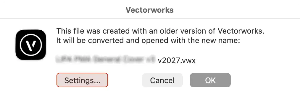
If you attempt to open a file created using an earlier version of Vectorworks, then this alert will be displayed. This is intended to warn you that you are doing this and to give you some options.

If you are happy to proceed….

  • click OK

However, if you have referenced geometry in the file or the file is quite old, then…

  • click Settings…

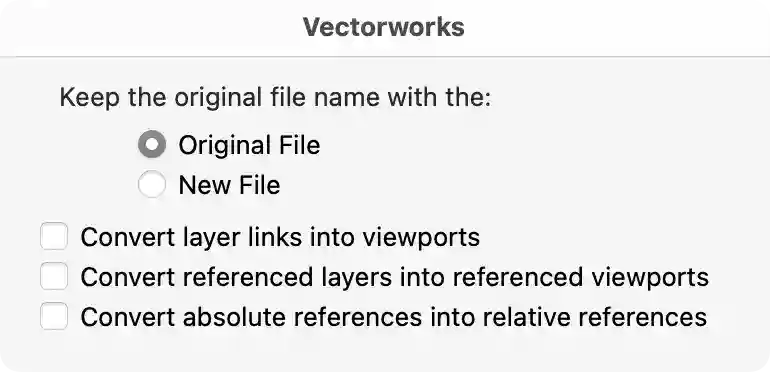
For the most part this dialog is self explanatory.

By default the program will open the file with the Original File name and append a V2026 suffix. 

If you choose the New File option, then the file that is opened will retain the original File name and the old file will be renamed with a suffix bearing the version year that it was made with.

References

These settings are for much older files, when a system called Layer Links was the only way to reference another document in the file.

  • Convert Layer Links into Viewports will place a Design Layer Viewport containing the Referenced file geometry on a dedicated Design Layer.
  • There are two Referencing workflows. Some users like to use the older Referenced Layers workflow. If that is the case, and you want to update to the more modern approach using Design Layer Viewports, then check Convert Referenced Layers into referenced viewports.
  • If you are Referencing files into a drawing it is advisable to use relative references. This will allow files to be moved around, and as long as the Source file and the Reference File are moved relative to each other, then all referenced files will continue to open.

It is important to realise that all referenced files need to be saved in the same File Format for this process to work.

So open and convert the Referenced (child) files first, and then open and convert the Parent file.

If you have many Files with references, then it is worth exploring the Batch Convert Command from the File menu.

SPOTLIGHT

Schematic Views

Schematic Views have seen a major overhaul this year. Schematic Views are the mechanism by which a designer can display the layout of Lighting Devices and other Rigging Loads in a clear and concise 2D format.

This ability existed in earlier versions of the program, going back to 2019, but many users found the concept hard to understand, and the results were often unpredictable.

This new version is vastly improved and lets users quickly get what they need while also providing a platform for finding creative ways to use them.

Cable and Power Planning

There are two significant improvements to this aspect of the program.

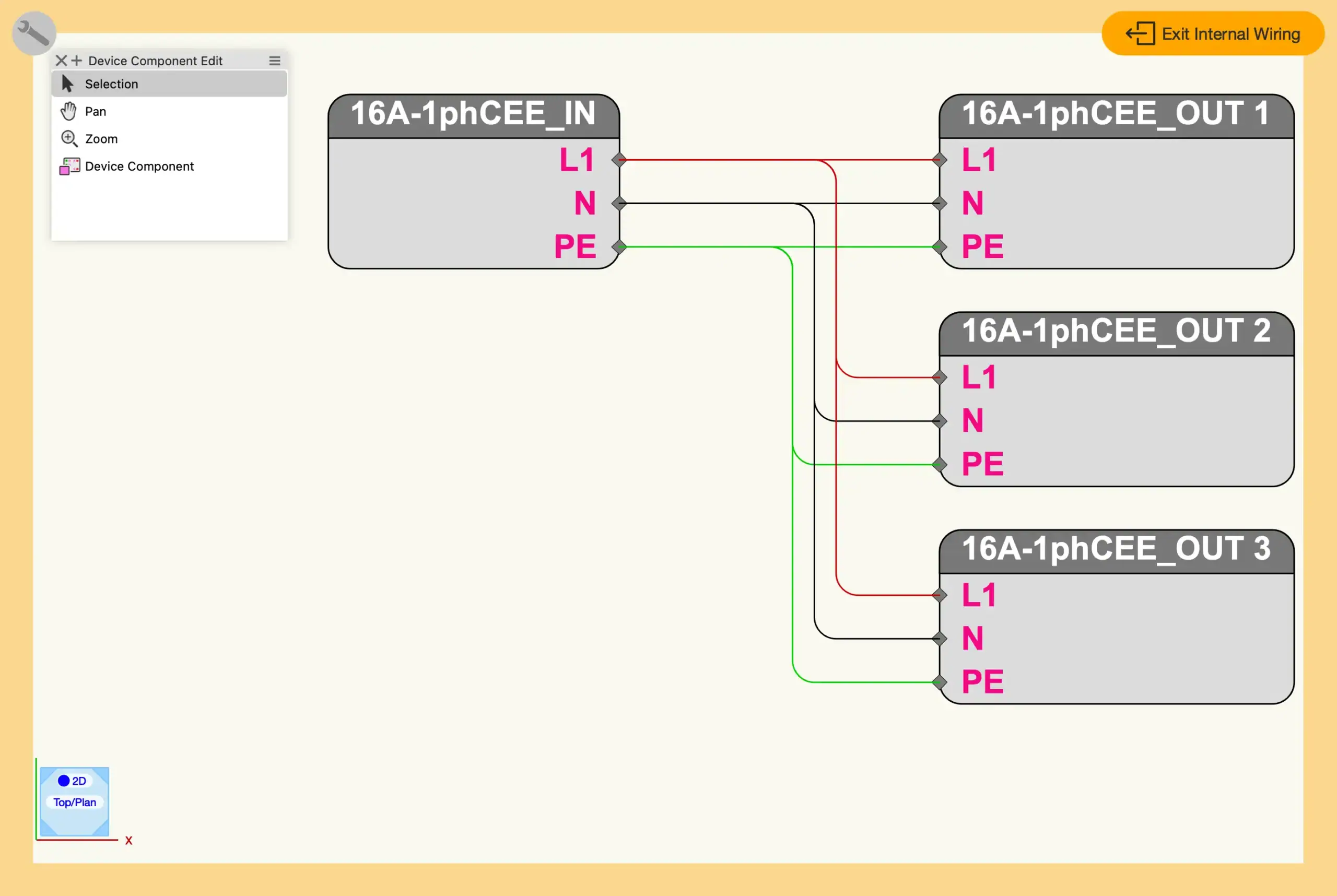
Distributor Edit Mode

Distributor objects used to be time-consuming to build and edit. This is because each component needed to be manually added and connected using plug-in geometry inside the definition Symbol

Now ConnectCad has added some functionality to these objects, and you can build distributors using ConnectCad diagrammatic components. 

Users will have two new Context Menu commands they can use with any Symbol listing in the Resource Manager

Users’ custom Distributors will be automatically upgraded to use this method, and existing component plug-in objects will be converted to groups.

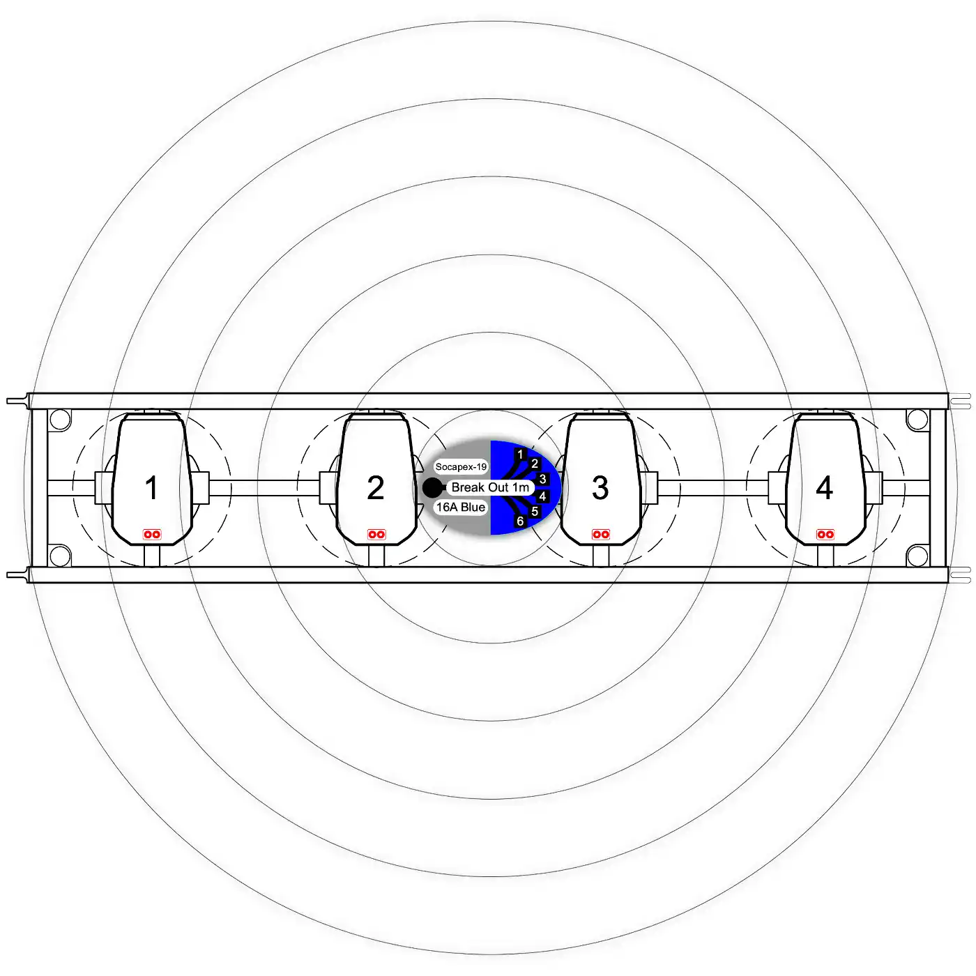
Breakout Length Circles

The lengths of output tails for Distributors can now be displayed visually by a Distributor object. Not only that, but cable calculations from distributors to their power loads will factor in the lengths of the breakout Tails.

This will make cable-length calculations even more accurate.

Widget Groups for Lighting Devices

The list of Parameters for Lighting Devices grows every year. This has made finding a particular parameter time-consuming.

Now all parameters are organized under collapsible headings, or Widget Groups, within the Object Information Palette. You can either accept the default Widget Groups or create your own.

Lighting Device Invert Pan/Tilt

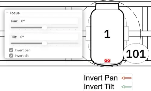
You can now invert the Pan and Tilt values for Lighting Devices individually. This makes mirroring focused Lighting Devices much quicker, and presetting invert parameters for Showcase and MVR export is now as simple as checking a box.

Because this is a Lighting Device parameter, you can easily show this requirement using Data Tags and Worksheets.

MVR & GDTF Improvements

Lighting Device Edit Dialog – Color and Gobos

The Edit Dialog for Lighting Devices has been updated so you can easily swap Gobo patterns for your own choices. These can now be exported as MVR devices for use in external visualizers.

MVR Export – Layer Filtering

You can now select only the Design Layers you want to export to MVR. This will hopefully save users time.

Ability to Export Truss and Blended Screens as GDTF objects

Screen, Blended Screen and Truss Objects can now be exported and imported as GDTF files. In the Edit Screen Image dialog for each Screen object, a new section lets you specify the relevant GDTF Data.

Searcheable Pull/down for selecting GDTF or LIT data

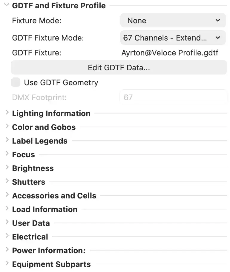
Lighting Devices use either LIT or GDTF data when used with visualizers such as Showcase or Augment3D. For these files to work, the correct data must be loaded into the Lighting Device using the Object Information Palette.

Until now, the search procedure for this data was a little prescriptive, but now a “wildcard” search has been enabled, so many more equipment options will be available.

MVR-xchange – Improved workflow

Those who use the MVR-xChange Palette will find that they can now refresh the Groups.

Fundamentals

These updated features are available to all users of the program.

Vectorworks Graphics Module Modernization

The Vectorworks Graphics Module (VGM) has been completely rebuilt, and every part of the graphics system has been redesigned. 

With the older graphics module, the computer’s CPU handled much of the workload of displaying the graphics we created. This meant that with large models, users experienced some stuttering in the on-screen output. Now, much of that work has shifted to the computer’s GPU, and Vectorworks has a much cleaner architecture to build on in the future.

For macOS users, Metal 3.1 is now fully supported. For Windows users, the new VGM utilizes Vulkan 1.3, which is compatible with most GPUs.

The improvements are quite dramatic across all types of output. If you are importing busy DWG files and navigating Shaded views with lots of lighting, this will be a significant improvement.

If for any reason your output relies on the earlier version, then there is an option in Vectorworks preferences to switch back to the 2026 VGM.

Vectorworks Texture Modernization

For years, Vectorworks has used its own proprietary Texture creation method. This has now been modernized so that it uses the OpenPBR industry standard. Please check back here in the next day or so when a separate section will be available which will introduce this new approach.

Line types

Complex Linetypes have always been a little tricky to deal with, especially when working with polygons and polylines.

Now they let shapes within the linetype flow around corners or wrap within the segments of polygons and polylines. This makes it much easier to get polished results when creating diagrams and annotating viewports.

Extrude along Path Command

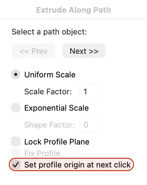
This command has seen its first update in twenty years. Now you can specify the exact point on the Profile geometry you want the Path object to use.

When you run the command and check this box, then when you press OK, the Profile will zoom to fill your drawing window and you can select an exact point on the Profile shape to use.

Fillet Tool

The Fillet Tool has been given an overhaul, and now filleting shapes is completely interactive, allowing you to make decisions based on how the object looks, rather than having to know an actual value.

Circle & Arc Tools

Like the Fillet Tool, these two tools have been given the ability to create interactive tangent Arcs and Circles based on their relationship to other shape objects. Both of these tools are quite fun to use, and they are definitely worth exploring.
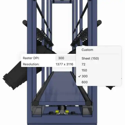
Viewport DPI

When Sheet Layer Viewports are set to a render mode such as Shaded or Renderworks, they display the rasterized results at a specific DPI. This has normally been set by default to 72 DPI and, more recently, to 150 DPI. 

Most users change this to something closer to 300 DPI, as this gives cleaner, more accurate results. 

However, making that change meant that the user had to change the setting for the whole Sheet Layer, and many users asked for a way to change it more locally.

Now you can, and there is a new set of parameters on each Viewport. You can still set the Sheet DPI in the usual way, but this adds extra control, which some people will find useful.

Non Plot Classes

Vectorworks is making some more incremental steps to make our files more exchangangable with the DXF/DWG file format. 

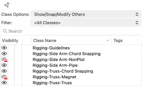
For years, AutoCAD has allowed some Layers to be set to Non plot. Vectorworks now supports this, and any imported DWG layers using this setting will apply it to the resulting Vectorworks Class.

This doesn’t apply only to imported geometry; native Vectorworks Classes can now be set to Non Plot if needed.

The Create Classes dialog now includes a checkbox; when enabled, it places a graphic next to the Classes visibility listing in the Navigation Palette, and anywhere else Classes are listed.

Any geometry that is assigned to a Non Plot Class will not be visible in Sheet Layer Viewports unless the Viewport is set to Wireframe, which includes Top/Plan.

DXF/DWG Import of Dynamic Blocks

Dynamic Blocks have been available in AutoCAD for years. In previous versions of Vectorworks, Dynamic Blocks were imported from DWG files as separate Groups.

Now Dynamic Blocks are imported as Dynamic Object Plug-in objects. You can edit them as much as you like, but for now you can’t create new Dynamic Plug-in objects. Currently, the only way to use them is to have access to a DWG file that contains them.

If you would like to try working with a converted Dynamic Plug-in object, then you can download one here.

FBX import

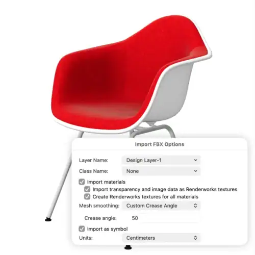
Vectorworks can now import the FBX file format. The FBX file format was developed as a way to store motion capture files and has been widely adopted by applications including Blender, 3DS Max, and Unreal Engine.

Although Vectorworks can export to this format, it could not import the files until now. When you import files, it retains all geometry and materials. You can convert FBX materials to Renderworks Textures.

Menu > Import > Import FBX

This makes importing assets from websites like Poliigon so much easier.

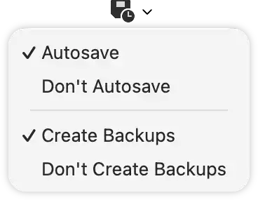
Autosave & Backup

Autosave has been enhanced a little.

You can now overwrite your current working file while creating backup copies. 

This is useful, especially if you have set a backup to occur every, say, 25 operations. If a user gets interrupted or doesn’t save and close the file for any reason, then no save or backup will be made until the work resumes. Now you can set the program to autosave after a set amount of time, so you don’t have to worry about a power failure or a crash if you haven’t clicked save.

The Quick Preference button has also been updated.

Purge Command

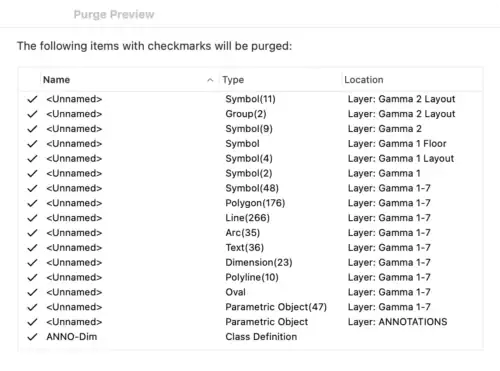
The Purge Command has seen a small but welcome update. Now, when you preview the items you are about to purge, the dialog summarizes the items by Type and Layer as opposed to listing every item in what can be a very long list.

If you have ever imported and then purged a large architect’s DWG file, then you will appreciate this small change.

Associative Dimensions

When a Dimension is associated with an object, then when the Object is moved or resized, the Dimension will move or update to reflect the change. The same is true when the Dimension is moved or resized.

This behavior caused problems if Dimensions were accidentally moved, as the dimensioned objects would also move, sometimes without the user realizing it.

Now, dimensioned objects will not move if the Dimension object is moved.

Design Suite

The updates are available to users who use any of the Design Suite "Fundamentals" upgrades. This includes Spotlight, Braceworks, Architect, and ConnectCad.

Graphic Legends

Graphic Legends have improved slightly.

  • It is now possible to use the same Unit overrides that are available in Data Tags.
  • Another improvement, inspired by Data Tags, is that you can now list SubParts of objects.
  • You can attach a Record to a Graphic Legend, and if the results match criteria you set within the Graphic Legend, then you can use the same Graphic Legend for different criteria of objects.

This has all sorts of uses for creating Graphic Legends to show Truss by a specific manufacturer or maybe Lighting Instruments by category.

Data Legends

Data Legends are a new addition to the program for 2027. They combine the functionality of Graphic Legends and Worksheets into an object you can add to Design Layers and Sheet Layers. This is an advantage over Graphic Legends, which only work on Sheet Layers.

Essentially, they work like Graphic Legends, except they have no image. The result is a highly customizable data reporting tool that many users will use as an alternative to Worksheets when Data needs to be presented repeatedly and quickly alongside your design.

Data Legends can be added to the drawing using the Data Legends Tool from the Annotations Palette.

Data Tags

Data Tags gets two new additions to the Mode Bar.

Coincident Picking Mode

When you have objects that occlude each other but nevertheless need to be tagged, this mode will provide a small dialog with a list of the coincident objects that are available under your cursor.

Tagging Order

When you automatically tag all eligible objects, the Data Tags are added according to the history of the tagged objects in the database. That is fine if you are just extracting the data, however, some users use Data Tags to incrementally number objects, so now there is a dialog that opens giving you a few tagging order options.

Data Visualization

Data Visualization Resources

Data Visualization has been upgraded, and you can now store Data Visualization settings in the Resource Manager.

Some users apply multiple Data Visualizations at the same time, and now you can create Data Visualization Sets, which can also be saved in the Resource Manager.
Auto-Color 

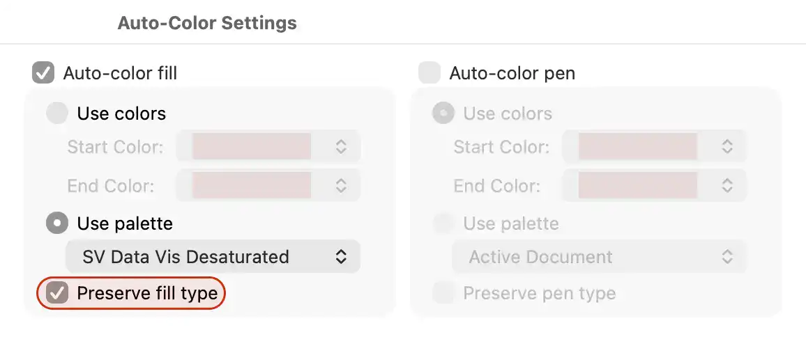
Auto-Color used to be a bit of a blunt instrument. When applying Auto-Color, any Fill Attribute settings such as “no fill” and opacity were overwritten all geometry was automatically treated the same. The user had to refine the settings so that “Retain original Fill” was applied. The same was true for Pen Attributes. 

Now the Color Settings dialog includes a setting to “Preserve Fill Type”. This will make creating Data Visualizations much quicker.

Data Tags

The attributes that you specify for objects in a Data Visualization can also be applied to any associated Data Tags.

User Interface

Midpoint Reshape Handles

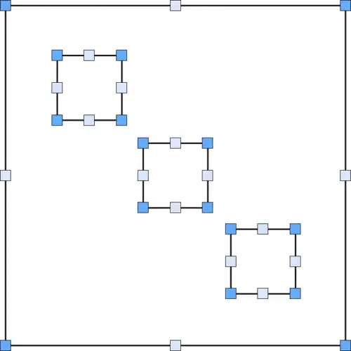
Most CAD programs can show the difference between the end and the middle of a vertex. Until now, Vectorworks did not, and it displayed all vertices as blue control points.

Now, the midpoint of a vertex is clearly defined using a lighter blue, which will be very helpful when using the Reshape Tool, especially when adding or removing vertices.

You can customize this color using the Interactive Settings section of Vectorworks Preferences.

Non-blocking Alerts

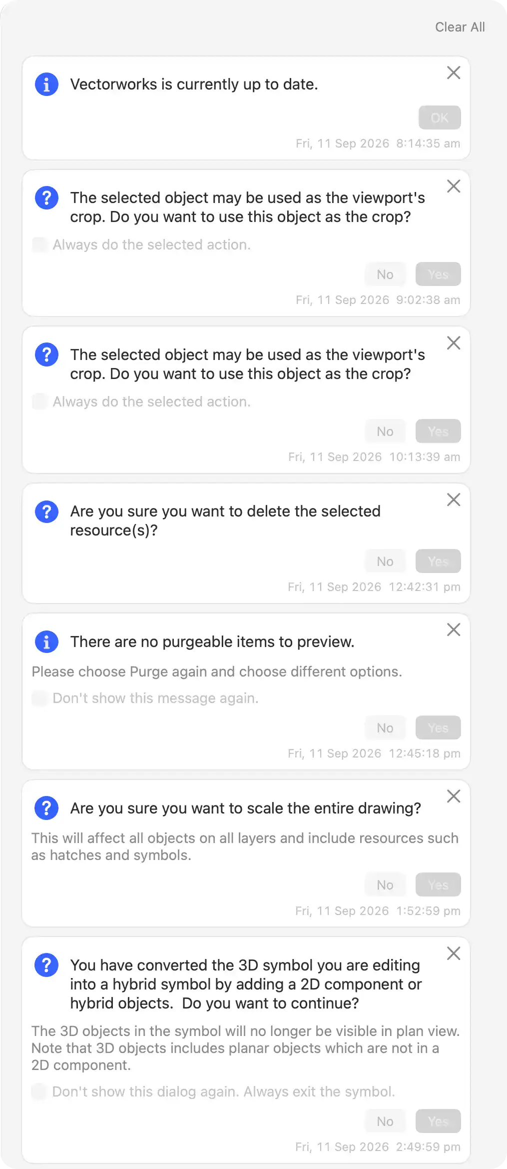
In previous iterations of the program, alert boxes would open and, until you dismissed them, interrupt your workflow. Most alerts now appear in the bottom-right of the Application Window, where they stay for a few seconds before moving to a longer list, which you can open by selecting the bell  icon.

From here, you can review the alert and, in some cases, decide whether to see it again.
Palette Docking

It is now possible to dock Palettes on any of the four sides of the Drawing Window.  Just drag any palette you want to dock, and it will be held inside a clickable Tab.

Workspace Management

Because Vectorworks has been developed over several decades, some Workspace palette behavior may have been inconsistent. A lot of backend work has been done to consolidate the work various engineering teams have done over the years. 

The front end has seen some small tweaks.

  • A checkbox has been added to the Workspace editor so that when editing a Workspace to maybe add a shortcut or rearrange the tools in a palette, you have a choice as to whether to save the palette positions with the changes you have made or not. This will help users who switch between different-sized screens, as well as CAD administrators who want to implement Workspace changes without changing the palette positions individual users may have set up.
  • Web Palettes like the AI Visualizer or the Exchange Palette were not part of the Workspace files. Now they are. 

Onscreen Temporary Controls

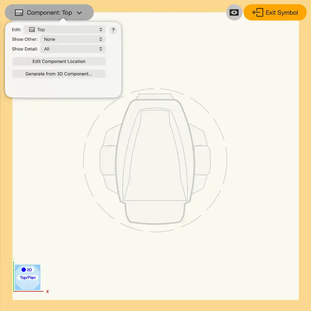
The palette in the Symbol component edit window has been replaced with a control bar permanently anchored to the top left of the window. All the functionality available in the palette in earlier versions is available here. 

Additionally, the right-click Generate 2D from 3D components command has also been moved here.

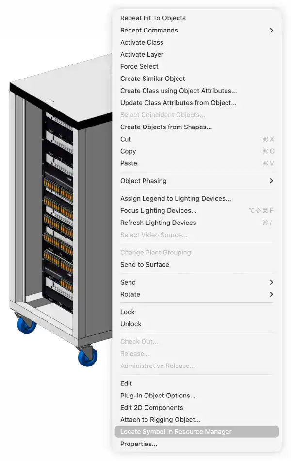
Locate Symbol in Resource Manager Command

Many Plug-in objects use Symbols as their geometry source. Before 2027, this only applied to Lighting Devices. Now, if you right-click on any of these plug-in objects, you can select the Locate Symbol in Resource Manager command, and the Resource Manager will open and the correct Symbol listing will be highlighted.

Vectorworks 2027